
Image ©2004 DiscoverHover
DiscoverHover CURRICULUM GUIDE #11
GEAR RATIO
© 2004 World Hovercraft Organization
| NAME | DATE |
In engineering, just as in everyday life, things are not always perfectly suited for every purpose. To use them effectively, compromises are required. For example, most engines run best at speeds faster than a hovercraft fan or propeller can spin without bursting. How do we reduce the rotational speed of the fan or propeller without reducing the speed of the hovercrafts engine? Gears and belts are a compromise that solves this problem.
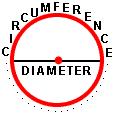
To make the concept of gears and gear ratio easier to understand, let’s first review some properties of circles. The radius of a circle is defined as the length from the center of the circle to the outside of the circle. If we draw a line that starts at one side of the circle, goes through the center, and then stops at the opposite side of the circle, we would have the diameter of the circle. The diameter is twice as long as the radius. Finally, if we measured the distance around the circle, we’d get the circumference. It turns out that the circumference is equal to the diameter multiplied by pi. Pi is often represented by the Greek symbol, π, and is approximately equal to 3.1415927… or the very strange ratio of 22 / 7 is sometimes used for rough calculations as it is close!
|
|
|
| Figure 11-1: Parameters of a Circle Image ©2004 DiscoverHover |
||
Now we can apply these concepts to examine how gears work. Look at the gears in the diagram. The radius of the gear is the distance from the center of the gear (where it rotates) to the outside of the gear. If gear A measures 24 cm [9.45 in] in radius and gear B measures 12 cm [4.72 in] in radius, then the radius of gear A is twice as large as gear B. We say that the gear ratio of gear A to gear B is 2:1. Additionally, we know that the diameter is twice the radius, and the circumference is π times the diameter, so if the radius of gear A is twice the radius of gear B, then the circumference of gear A is also twice that of gear B. In the diagram of the two gears you can see that twice the circumference means that the gear has twice the number of teeth.
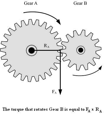
Figure 11-2: Gear Motion
Image ©2004 DiscoverHover
Imagine that gear A starts to rotate. As its teeth touch the teeth of gear B, a force is exerted. In the diagram this is shown as FA. If gear A rotates clockwise, the teeth of gear A push downwards on the teeth of gear B. This will cause gear B to move counter-clockwise. In this case, gear A is called the driving gear, and gear B is called the driven gear. If the gear ratio of A to B is 2:1, then there are twice as many teeth on gear A as on gear B. If you look where the two gears connect, you can see that the gear teeth alternate, that is, a tooth from gear A is followed by a tooth from gear B, then one from gear A, then one from gear B, and so on. Since we said that gear A has twice as many teeth as gear B, then it will take twice as long for gear A to rotate once all the way around. This means that gear A will rotate two times slower than gear B. This is very useful because we now have a way of speeding up and slowing down torque rotation!
We said that a gear that is half the size of another will rotate twice as fast. A gear that is one fourth the size of another will rotate four times as fast. This relationship is called a reciprocal. For example, 1/2 is the reciprocal of 2, and 1/4 is the reciprocal of 4. To find the reciprocal of a given number, you divide one by that given number.
Reciprocal of number = 1 / number
The gear ratio of two gears is the reciprocal of the ratio of their rotation speeds.
To calculate torque on two gears, use the formula for torque.
Torque = Force × Length of lever arm
Gear A is exerting a force on gear B, but remember Newton’s
Third Law of Motion states that gear B will, in turn, exert an equal force back on gear A.
This means that the force on each gear is the same. The force applied to each
gear occurs where the gear teeth are in contact on the outside of each gear,
so the length of the lever arm for each gear is equal to the radius of the gear.
Since the radius of gear A is twice the radius of gear B, the torque on gear
A will be twice the torque on gear B. This is very useful because we now
have a way of enlarging or reducing torque!
Let’s review what gear ratio means. If the gear ratio of gear A to gear
B is 4:1, we know the following: the radius, diameter, and circumference of
gear A are all four times larger than gear B. We know that the torque on gear
A will be four times greater than the torque on gear B. Finally we know that
gear A will rotate at one fourth the speed of gear B. A larger gear
will rotate slower than a smaller gear and have a greater torque, and the two
gears will rotate in opposite directions.
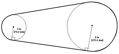
Figure 11-3: Pulleys with a Belt
Image ©2004 DiscoverHover
When working with pulleys connected by a belt, the principles behind gear ratio, rotation speed, and torque are exactly the same. In the diagram, the pulley on the left has a radius equal to half the radius of the pulley on the right. This means that the pulley on the left will rotate twice as fast, but will have only half the torque.
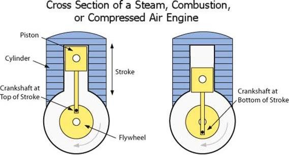
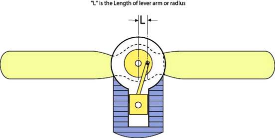
Figure 11-4: Application of Torque in Combustion Engines
Image ©2004 DiscoverHover
Torque and gear ratios are important in designing what is called the hovercraft’s transmission. Lightweight engines produce most of their horsepower at high rpm (revolutions per minute). Unfortunately, this would spin a propeller too fast for safety. To get maximum thrust from a propeller, the tips of the blades should rotate between 1100 and 1150 km/h [683.4 – 714.5 mph]. At speeds above this, the flow of air begins to detach itself from the propeller, decreasing efficiency and increasing noise. Propeller tip speed on a hovercraft should never run higher than 641 km/h [460 mph] tip speed for safety. It's often necessary to use a belt or gear driven system to slow the propeller but still let the engine reach its maximum horsepower. Using a small pulley on the engine and a larger pulley on the propeller will allow the propeller to turn more slowly than the engine. This is ideal for a two-blade or four-blade propeller, since they produce more thrust at slower speeds. They also produce less noise and develop more thrust per horsepower than fans with many blades.
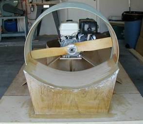
Figure 11-5: Propeller works due to application of torque
Image ©2005 DiscoverHover
Recall that the pitch of a propeller refers to the angle at which it is set, and a greater pitch means that the propeller can push more air and produce more thrust. Pushing greater amounts of air, however, requires more torque. If the pitch of the propeller is too great, it will strain the engine, making it unable to reach its maximum rpm. Too great a pitch can also cause the blade to "stall" where upon it will push almost no air. Choosing the right propeller pitch to maximize thrust while still allowing the engine to reach its maximum rpm is a very important step in designing a hovercraft.
The graph below is an example of what the characteristics of an engine and propeller could look like. The red curve shows the power output of the engine. Notice how it increases as rpm increases until it reaches a maximum at about 3400 rpm. It then quickly decreases as the speed continues to increase. The green curve represents how much power must be supplied to the propeller in order to keep it turning at the given speed. Notice how the faster the propeller spins, the more power is required. At lower rpm’s the red curve is higher than the green curve, meaning that the engine produces more power than is needed to keep the propeller spinning. At about 3700 rpm, the two curves intersect, meaning that the engine produces just enough power to keep the propeller spinning at that rpm. This is the most efficient engine speed at which to run because no engine power is being wasted. Notice that at higher rpm’s the engine cannot produce the horsepower necessary to power the propeller.
Figure 11-6: Required Propeller Power vs. Engine Output Power
This is only an example power profile. In fact, this graph could change drastically
depending on the conditions in which the hovercraft is operating. For example, the
propeller’s curve can change significantly depending on whether wind is blowing,
and in what direction it’s blowing. No matter how the propeller or engine
power profile changes, the engine speed at which the two curves intersect will
indicate the point of maximum efficiency and maximum static thrust.
Quiz Question:
| ©2005 World Hovercraft Organization All rights reserved. Copies of this Curriculum Guide may be printed for classroom use exclusively by DiscoverHover registered members. This Curriculum Guide and all materials contained in the DiscoverHover web site are protected by copyright laws and may not be reproduced, republished, distributed, or displayed on any other web site without the express prior written permission of the World Hovercraft Organization. |